Dimensioning Sheet Metal Flat Pattern

New To Sheet Metal Looking For Feedback About Dimensioning Autodesk Community Inventor
Sheet Metal Layout Tip Dimension To Formed View Not Flat Pattern

How To Define The Mbd Data Of Sheet Metal Parts Engineers Rule

What Happened To My Flat Pattern View Computer Aided Technology

Solved Sheet Metal Drawings Dimension Problem Autodesk Community Inventor

Drawing The Inventor Flat Pattern
The sketch and locating dimensions are retained.
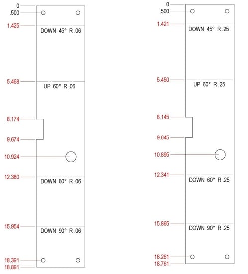
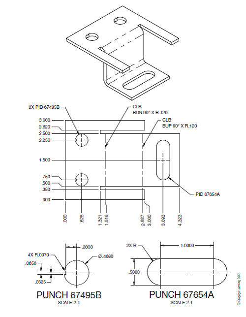
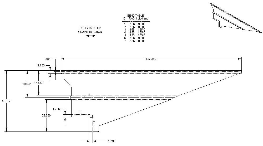
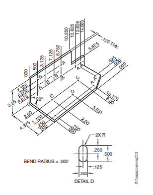
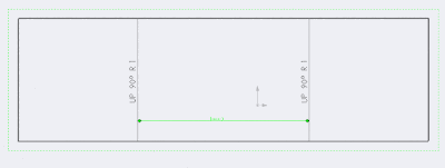
Dimensioning sheet metal flat pattern.

R11 Flat Pattern Vs Iv2008 Flat Pattern Autodesk Community Inventor

Solved Flat Pattern Dimensions In Parts List Again Autodesk Community Inventor

Standard For Dimensioning Sheet Metal Flat Patterns Induced Info

3d Cad Modeling Of Sheet Metal Parts

Practical Machinist Largest Manufacturing Technology Forum On The Web

Layout And Forming Part One
Solved Instructions 1 From The Selected Sketch Draw The Chegg Com
Fabrication Formulas Sheetmetal Me

Reading Precision Sheet Metal Prints Ppt Download

Seven Improvements For Sheet Metal Drawings Drew Cad Booster

Drafting For Electronics Projection And Dimensioning

Sheet Metal Annotations In Drawings Inventor 2016 Autodesk Knowledge Network

Dimension Flat Sheet Metal Youtube
Sheet Metal Dimensioning Standards
2012 Solidworks Help Creating Drawings Of Sheet Metal Parts
Solved Instructions 1 From The Selected Sketch Draw The Chegg Com
Add Dimensions To Bend Lines Using Solidworks Api

Inventor Sheet Metal Drawings Youtube
Https Encrypted Tbn0 Gstatic Com Images Q Tbn 3aand9gct3zfazig75npdzpw Xd R1gzsyacdxiq4uba7vtl4pdytnncyc Usqp Cau

Sheet Metal Drawing Sheet Sheet Metal Sheet Metal Drawing Drawing Sheet

Solidworks 2015 Bend Lines Youtube
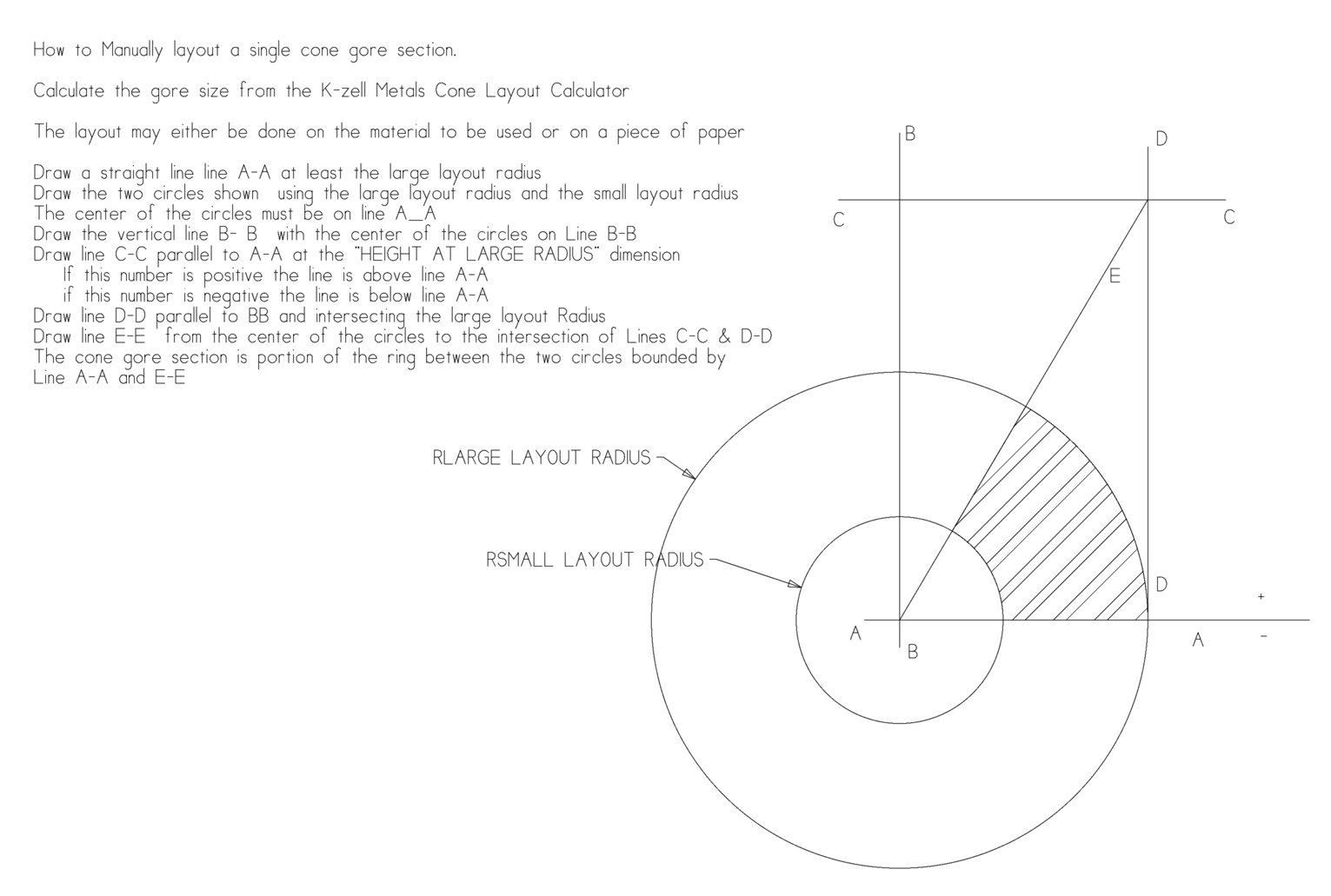
Cone Calculator Sheet Metal Flat Layout Formula K Zell Metals

Add Flat Pattern Dimension For All The Instances At A Time For A Sheet Metal Part In Creo Parametric Youtube
Https Docs Plm Automation Siemens Com Data Services Resources Se 109 Se Help En Us Selfpacedext Pdf Mt01419 Pdf
Source : pinterest.com
